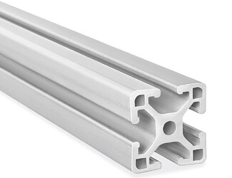
While 3D printing is great, some designs warrant the use of something more robust. Aluminum extrusions or “T-slot rails” like the following (ULine) can be useful in this regard.
A few resources that may be of interest:
Some questions for everyone for what they’re doing / have found to be good conventions:
- which extrusion designation(s)? (e.g., 2020 aluminum extrusions)
- What unit lengths? (e.g., 25 mm increments)
- Any recommendations when doing CAD designs? (e.g., importing from McMaster Carr in Fusion 360)
Links to example products would be welcome, maybe even an example design file if someone is willing to share.
cc @dlin @yangcyril.cao @kthchow @roastyghosty @chattrick
Highly related: What are some ways to fixture devices relative to other devices? (and piggybacking off of this comment specifically)
EDIT: nice practical recommendations from @kthchow at GitHub · Where software is built.
Calvin from NRC here. We use both metric and imperial designations here - sometimes you don’t get to be picky with what you need to mount onto it.
- For imperial, we’ve been using widths/heights multiple of 1 or 1.5 inches. Slot size 8 since it’s also a common size for connectors.
- For metric, I would be fine working with any x0y0 designations (both x and y are integers). 20xx are the most common here, used for framing enclosures. I don’t like uncommon standards, such as 45mm increments typical in Vention structures.
- I don’t have strong opinions about discretizing height. Material stock is often sold in imperial thicknesses (Canada), while experimental convention often calls for metric designs. For designs resembling a stack (e.g. fuel cells, membrane electrode assemblies, etc.), I find myself gravitating toward designs that are metric in the X-Y plane but imperial in the Z axis. By extension, there may be a world where T-slot extrusion lengths would be better discretized in inches even if it’s a metric designation.
Basically, I would love to play SDL Minecraft and restrict designs to 20xx, say 20mm increment heights, but I’m not confident we always have the luxury to do so.
1 Like
I like to combine 3d printing and 8020-style aluminum extrusion when solving mechanical design problems. Size tends to be “whatever we’ve got lying around”, or the 45mm Vention stuff that we’ve used pretty heavily at RPL, as the case warrants. I’ve harvested 10mm from defunct 3d printer carcasses, for instance, and used…I want to say 25 or 30mm that was on hand in the machine stop
Because I’m terminally programmer-brained, I use OpenSCAD for most of my CAD work, and have found this library very useful for 8020: GitHub - sid5432/8020parts: Some Openscad models for 8020.net parts.
Agree with @roastyghosty that standardizing is a beautiful dream often denied to us mere mortals.
1 Like
At the AC because we’ve had the luxury of building from scratch, we’ve been able to control the imperial/metric selection a bit. @yangcyril.cao and @clascclon decided to use 25mm width extrusions combined with thorlabs optical breadboards with 25mm spacing, and that has kind of proliferated across all AC SDL labs in Toronto. All nuts and bolts are M6 for both breadboards and extrusions, making it easier to stock all types of lengths of M6. That’s been nice, but like some of the other comments above have mentioned, this is not standard or commonly stocked, so it takes a bit longer to get here.
For solidworks, there’s a weldments package that makes it really easy to design extrusion assemblies from a 3D sketch. I don’t believe something similar exists in fusion and I haven’t bothered checking other CAD software.
I’ve found this a good intro resource in the past. I don’t believe you can buy directly from this website, but they should list local redistributors. And a website like mcmaster stocks these parts (i believe)
Some labs are using vention extrusions. They are all 45mm width and the lengths are readily available to ship in 45mm increments.
1 Like
I love using aluminum extrusions for adjustable setups, anything that requires a solid linear constraint, or things with motion elements . Beyond a certain size 3D printing becomes impractical due to strength limitations, print time, and smoothness (I’ve found that many 3D printed motion components can work if your printer is very dialed, but generally it isn’t worth the hassle).
I’ve recently been building some test setups using 2020 extrusions that I source from McMaster, as they have a good number of accessories, as well as the usual instantaneous shipping. Their length increments are pretty lacking though. My decision to use 2020 was mostly motivated from it being the standard for a lot of 3D printers, so I figured there would be good number of preexisting designs I could use to mount stuff to them.
I also mount these to breadboards with M6 hardware. Found some good printed mounts for that on thingiverse.
On the CAD side I’ve had no trouble importing from McMaster into Onshape and working from there. Getting the assembly constraints set up doesn’t take too long and then designing around that becomes pretty easy.
1 Like
